Power
– Power Factor
04/09/2020
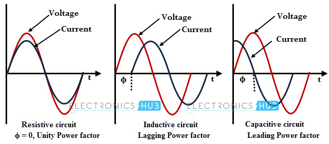
Power Factor measures how far current lags or leads voltage and ranges from 0 to 1. In a purely resistive load, PF is 1.
Examples of resitive loads include
incadescent lighting and resistive heaters.
Capacitive loads include capacitor banks, buried cables and capacitors
used to start motors. Inductive loads
include motors, transformers, solenoids, contactor coils, relays, generators,
and flourescent and LED lighting. As you
can imagine, inductive loads dominate most manufacturing facilities.
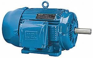
Manufacturing facilities have inductive loads mainly due to the coils in motors used to power pumps, fans, compressors and conveyors. Inductive loads resist a change of current causing the current to lag voltage. With an inductive motor load, some energy called Reactive Power (VAR=Volt Amps Reactive) is used to build the magnetic field and then returned to the circuit when the magnetic field collapses. Building and collapsing the magnetic field results in hysteresis losses in the iron core that results in wasted heat. The useful power available for motor torque is called real power (W=Watts). The Apparent Power (VA) is the vector sum of VAR and Watts.
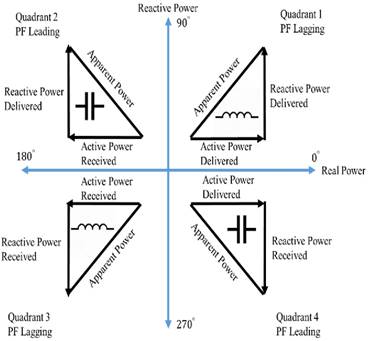
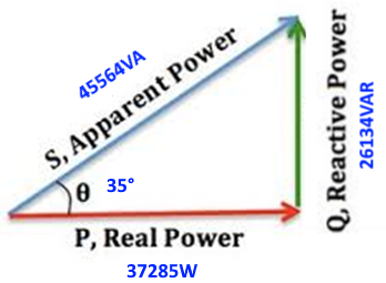
In most facilities, Quadrant I PF lagging for the motor is the dominant form (with Net Reactive Power delivered to develop the magnetic field of motors). Consequently, quadrant I vector diagram is analyzed below.
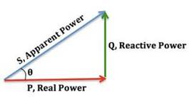
The Reactive Q (VAR) and Real P (KW) vectors form a triangle with Apparent Power S (VA) as the hypotenuse.
Power Factor= P/S.

![]()
![]()
![]()
![]()
![]()
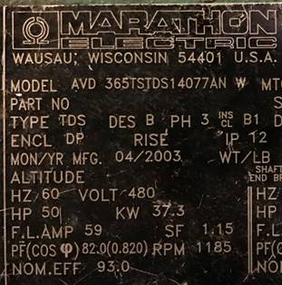
S=Apparent Power=480V x 59A x √3 x .93eff = 45564VA
P=50HPx745.7W/HP=37285W=37.3KW
PF=COSΦ=P/S=37285W/45564VA=0.82, Φ=COS-1(.82)=35°, COS(35)=0.82
Q= 45564VAxSIN(35°)=26134VAR, S=VA=√(372852+261342)=45.5KW
Wires must be size to Apparent Power (VA), and not Real Power (W), so the more you can increase the Power Factor (PF), the less current the motor will use per HP.
Real Power Current=37285/(480Vx√3 x .93eff)=48A used for real power
Reactive Power Current=26134/(480Vx√3 x .93eff)=34A used for reactive power
But the wire must be sized for Apparent Power Current=59A
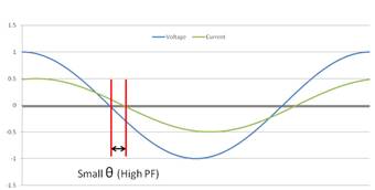
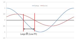
When an induction motor is heavily loaded (left), the voltage and current waveforms are nearly in-phase (small displacement), and power factor is high. When the motor is lightly loaded (right), the wave forms are out of phase (large displacement) and power factor is low.
In an AC induction motor, power is supplied directly to the stator and a magnetic field is induced in the rotor. The power supplied to the stator is referred to as “real,” or “active” power because it produces torque. The power used to induce the magnetic field in the rotor is referred to as “reactive” power because it does not actively produce work. The combination of real power and reactive power is referred to as “apparent” power. Real, reactive, and apparent power are often depicted on the power triangle. The amount of real power required by an induction motor varies with the load, but the amount of reactive power (power required to generate the rotor’s magnetic field) is constant regardless of the load. Thus, when an induction motor is lightly loaded, the ratio of real power to apparent power decreases, resulting in a lower power factor.
Capacitor banks can be added to the facility’s power distribution to increase the overall power factor.
Q: Why does the utility care how efficiently a plant or equipment uses the power it supplies?
A: Because low power factor causes higher line currents, which put more stress (primarily in the form of heat) on cables, transformers, and other equipment. Also, the lower the power factor, the more apparent power (kVA) the utility must supply to meet the real power (kW) requirements.